Shopping List This is what you'll need to build a receiver
TSOP 1740 (or equivalent)
1N4148 rectifier diode
5.1 1/4w zener diode
4.7 uF 10v electrolitic capacitor
100 Ohm 1/4w Resistor
4k7 Ohm 1/4w Resistor
DB9 female serial connector
DB9 plastic cover
small piece of thermo shrinking coating
Schematics This is the schematic diagram:This layout should help you follow the instructions. IC1 = TSOP 1738 +-----------------------+ 3 | data > +-----------------------------------------------+ | | R1 (4k7) | | | ____ | | | +---|____|--+--o DCD | | | | ______________ | | D1 (1N4148) | / | R2 (100) | | ( | 2 ____ | | /| | \______________ + +----------+----------+---|____|----+-----|< |-----o RTS | | | + | | \| | | __|__ | __ | | ===== | DZ 5.1v | /| | | | - +-------------------|< |--+--o GND | | 1 | _| \| | | - +----------+------------------------------------+ +-----------------------+ C1 (4.7uF) Serial port pinout Name 25-pin 9-pin -------------------------------- TxD 2 3 RxD 3 2 RTS 4 7 CTS 5 8 DSR 6 6 GND 7 5 DCD 8 1 DTR 20 4This version also works on serial ports that drive low current (such as the serial port on the via EPIA 800 MotherBoard).
There is a nicer picture of the schematics amongst the screenshots.
Instructions Howto proceed in building the device: These instructions are refered to a DB9 serial connector, be carefull if you are using a 25 pin connector.
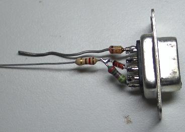
- Step1 Snip one side of the 4k7 resistor wire so that you have just enough space to solder it on the serial connector and solder it to pin 1 (DCD)
- Step2 From the rectifier diode (iN4148) snip the wire on the opposite side of the bar and solder it on pin 7 (RTS)
- Step3 Do the same to the zener and solder it to pin 5 (GND)
- Step4 Bend the 4k7 resistor and rectifier diode towards eachother so that the wires cross tuching eacother and snip them leaving enough space to solder
- Step5 Snip one side of the 100 Ohm resistor and solder it on the wires you jus crossed
- Step6 Bend the other end of the 100 Ohm resistor towards the unsoldered side of the zener diode and snip the wires leaving just enough to solder them together
- Step7 Once you have done this these components will hold eacother so that you can easily solder the oter 2 components without having things moving around
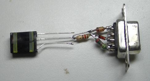
- Step8 Now it is time to decide how things will fit in the cover, generally I like the TSOP 1740 to come out of the cover from where the wires normallu do. If you solder pin 2 of the TSOP directil on the 100 Ohm resistor this should get you out of the cover, if not use some of the wires you snipped
- Step9 Solder one of the wires you snipped on pin 3 of the TSOP
- Step10 Slide the small piece of therno cover on the pin 3 of the TSOP and solder it to pin 1 (DCD) using the extension you just soldered
- Step11 Bend the wires on the capacitor close to it so that they bothe point to the rear end
- Step12 Now take care on how the capacitor will fit in the cover, snip the wire on the positive pole so that you can solder it to pin 2 of the TSOP ans snip the negative side so that you cav solder it to pin 5 (GND)
- Step13 Solder pin 1 of the TSOP on the negative side of the capacitor, this way you will use the wire as an extension to GND
- Step14 Place the cover and it's done.